6F5P SET Amplifier
Author: Dmitry Nizhegorodov (dmitrynizh@hotmail.com). My other projects and articles
|
|

|
1. In Brief
Single-Ended Triode (a.k.a SET) amplifier producing 1...1.5W into 8 ohm load. Uses two Russian deflector combo 6f5p tubes wired as triode.
2. Introduction
|
6F5P is Russian TV deflection triode/pentode combo tube, somewhat like ECL85/6GV8. If the pentode section is connected in triode mode, the tube provides a great playground for experiments with 2-stage SET designs on a "dime". It is no joke, however. The plate currves are very linear, reminding 45 or 2A3, input capacitance is low and the plate resistance is < 800 Ohm.
The schematic is as studied with SPICE in [4], with the following changes:
|
The power supply uses ultra fast diodes. RC filters a separate for each channel. 
|
For those preferring tube rectifiers - it makes sense to organize the supply around the theme of paper and oil capacitors and filter chokes:  This supply needs a ~600V CT transformer with a winding for the heater of EZ80. EZ81 (6CA4) can be used too; it is more robust but needs more heater power. A good choise is 6X5. 5AR4/GZ34 can be used, too (different pinout filament supply: 5V, 3A), but it is an overshoot. In case of EZ80 and 81 heater voltage is 6.3V and may be taken from the same coil that feeds 6F5Ps, although it is preferable to use a separate coil. If the same coil is used, pins 3 and 4 must be disconnected. One 6X4 per channel can be used as well. This supply needs a ~600V CT transformer with a winding for the heater of EZ80. EZ81 (6CA4) can be used too; it is more robust but needs more heater power. A good choise is 6X5. 5AR4/GZ34 can be used, too (different pinout filament supply: 5V, 3A), but it is an overshoot. In case of EZ80 and 81 heater voltage is 6.3V and may be taken from the same coil that feeds 6F5Ps, although it is preferable to use a separate coil. If the same coil is used, pins 3 and 4 must be disconnected. One 6X4 per channel can be used as well. The chokes are 5...9H. An excellent choice is to use 2 TW3 output transformers as chokes.
|

|
This snubber circuit is optional. It can help to reduce hum or hiss that some tubes may produce due to heater-to-cathode leakage.
|
3. Parts
One of the aims of this project is reproduceability. All parts are easy to find and inexpensive. Except for large-value capacitors, all parts are NOS soviet production, still available in Russia or Ukraine. Thus, the output transformers, TWZSH (aka TW-3SH), are available in Ukraine at electronic markets and so are 6f5p tubes. The power transformer is TAH6, rated at 56W, offering 2 6.3V, .9A windings and a 520V, 70mA, center-tapped coil. The rectifier is solid state - partly for simplicity, partly because TAH6 does not have enough filament power to drive a tube rectifier. Rectification is full-wave, performed by SF36 - super fast (50ns reverse impulse) low noise 3A, 400VRMS diodes. The PS filter is Pi-type, formed by a common 100uF electrolytic capacitor, and a 1.2k, 94uF filter for each channel. All resistors are carbon, 1/2 to 2 W. Signal capacitors are paper BMT. Paper & oil K40-y9 is another choice. Electrolytics are Samsung, rated at 400V. Rubicon capacitors is another and better choice.
4. Construction
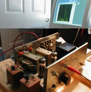
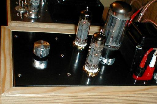
The chassis is constructed from aluminum L-shaped extrusions. The front extrusion is the the "front panel", hosting the double volume pot and two "mood" controls (driver bias pots).  These pots also allow to adjust balance by +-3db. Behind that the input jacks are mounted, close to the tubes. Behind them two output transformers are located at 90 degrees to the power transformer. The speaker posts are placed immediately after the output transformers. These pots also allow to adjust balance by +-3db. Behind that the input jacks are mounted, close to the tubes. Behind them two output transformers are located at 90 degrees to the power transformer. The speaker posts are placed immediately after the output transformers.
|
The rear extrusion was drilled to host power cord socket, power switch and fuse holder.  The rectifier diodes are soldered directly onto the power transformer lugs. The rectifier diodes are soldered directly onto the power transformer lugs.
|
The power supply is visibly detached from the signal circuit. The space between the power transformer and the output transformers can be occupied by paper and oil bypass, ultrapath or B+ filter caps - these are all possible upgrades.  Another way to use this space is to host a small filament transformer, providing current sufficient for a tube rectifier, which can be located in the space by the power transformer side. Another way to use this space is to host a small filament transformer, providing current sufficient for a tube rectifier, which can be located in the space by the power transformer side.
|
Soldering is almost universally point-to-point and directly onto the tubes, with the exception of the bias resistors and bypass caps of the power stage which are mounted on bias cap switch. The channels are wired symmetrically. Each channel has its own ground bus, short in length, connected to the input socket and not connected to the aluminum chassis.  Most parts are soldered on the bus in close proximity (< 20mm) of these points thus forming "star grounding". The power supply is also symmetrical (common rectifier, split filters) and has its own ground bus. The power supply bus is connected to the chassis and via separate wires - the grounds of each channel. Most parts are soldered on the bus in close proximity (< 20mm) of these points thus forming "star grounding". The power supply is also symmetrical (common rectifier, split filters) and has its own ground bus. The power supply bus is connected to the chassis and via separate wires - the grounds of each channel.
|
Two wooden blocks are attached to the side L extrusions. Those shown on the picture are prototypes.  The final version will sport more exotic wood, with access to the binding posts cut through the wood. Also, missing on the pics are the top cosmetic covers The output transformers are supposed to be covered with metal boxes, and so is the power transformer. the remaining top surface can be covered with small anodized aluminum panels, ceramic, copper, nickel alloy, etc. The final version will sport more exotic wood, with access to the binding posts cut through the wood. Also, missing on the pics are the top cosmetic covers The output transformers are supposed to be covered with metal boxes, and so is the power transformer. the remaining top surface can be covered with small anodized aluminum panels, ceramic, copper, nickel alloy, etc.
|
5. Measurements
We loaded the amp with 8 ohm, 2W resistors and obtained distortion data and frequency sweeps. The results are below. All data were obtained with 0db level corresponding to the output signal amplitude at which the amplifier starts clipping, which is the amplitude that gives raise to lots of high order harmonics. Unless specified, the output level is -3 db under the level of clipping.First, the spectrum data for various settings of the bias, load and bypass controls. Some combinations offer interesting possibilities for tone experiments.

|
|
|
set
|
Bypass caps yes/no
|
Driver load res value
|
Driver bias res val
|
Results
|
|
1
|
No bypass
|
47k load
|
1.6k bias
|
THD: 1.8%. We see highish THD, "Classic SET" spectrum with 2nd harmonic dominating. Intermediate position of the bias pot did not offer much differences in picture.
|
|
2
|
No bypass
|
47k load
|
3.8k bias
|
THD: 7.4%. Classic SET spectrum with 2nd harmonic dominating, high THD.
|
|
3
|
No bypass
|
47k load
|
bias ~ 2,5k
|
THD: 4%. Intermediate positions of the bias pot did not offer much differences in picture.
|
|
4
|
No bypass
|
77k load
|
1.6k bias
|
THD: 0.33%. Low distortion, very good spectrum, at -3db, same across the volume range. At very low volume, interestingly, 2nd drops very low: at -20 db - 2nd only a bit higher than 3rd, at -40db they are equal.
|
|
5
|
No bypass
|
77k load
|
3.8k bias
|
THD: 3.3%. SET character, higher 2nd harmonic level, hence more THD.
|
|
6
|
No bypass
|
77k load
|
bias ~ 2.5k
|
THD: ~1.5%. With deeper driver bias, distortion goes up. The very minimum of the 3rd (and higher odd) harmonic is at 1.6k position, hence it is the best dial for this config
|
|
7
|
Bypass
|
77k load
|
3.8k bias
|
THD: 0.79%. SET character, evenly diminishing products, fairly low THD.
|
|
8
|
Bypass
|
77k load
|
1.6k bias
|
THD: 2.17%. SET character. notice *huge* distance between 2nd and 34rd. while it is big at -3db, it is even more appealing at under -10db - high products drop to > -80db wrt the base.
|
|
9
|
Bypass
|
77k load
|
2.8k bias
|
THD: 1.54%. The lowest 3rd across the board - for ~ 2.8 - 3 k bias.
|
|
10
|
Bypass
|
47k load
|
1.6k bias
|
THD: 1.52%. Good space between 2nd and 3rd, 3rd lower than 4th, which is very good
|
|
11
|
Bypass
|
47k load
|
3.8k bias
|
THD: 1.53%. About the same level of 2nd and THD, but 3rd is comparatively much higher, and it stays that way across volume range, so 1.6 is better here
|
|
12
|
Bypass
|
47k load
|
3k bias
|
THD: 0.48%. Shift towards Push Pull character.This dial offers the lowest THD for the bypass, 47k combination, but alas at the expense of the 3rd. Compare -73dB (1.6k) with -60db here. This is harmonic cancellation at work, with its pluses (low THD) and minuses (spectrum drifting from SET to PP, with higher percentage of odd harmonics).
|
These patters are mirrored by the other channel as well.
The frequency response plot into 8 ohm resistive load, with the bypass cap, at full power is 0..-3dB in 30Hz-20kHz region; with bypass cap disconnected: 0..-2dB in 30Hz-20kHz region.
More detailed data is in [5]
6. Variants
This design was repeated, with some variations, by me and by friends. Here are a few picks.
San Francisco prototype

|

|
Viktor Dodatko, Dnepropetrovsk:

|

|
Orest Baidan, Mountain View:

|

|
7. References
[1] http://www.tubes.ru/techinfo/GlassTubes/6f5p.html[2] http://www.next-power.net/next-tube/DataSheets/tubes/6f5p.djvu
[3] http://www.dmitrynizh.com/tubeparams_image.htm
[4] SPICE simulation of this amp 6f5p-set.htm
[5] measurement details 6f5p-set-impl-2.htm
Author: Dmitry Nizhegorodov (dmitrynizh@hotmail.com). My other projects and articles
 (1) output bias resistors were adjusted for specific tubes, for best results, assuming the bias voltage ~30 V and current 35-40mA; (2) bypass caps are 47uF; (3) instead of 2k driver stage autobias resistors were used series connected 1.6k constant resistor and 2.2k pot in rheostat wiring - one leg to the 1.6 resistor, two other legs - shorted and connected to to the ground (4) driver stage load is 2 resistors in series, 47k and 30k, with a switch shorting the 30k resistor. (5) power stage bypass caps can be disconnected with a switch.